How To Set Up A Swimming Pool Pump
Step one
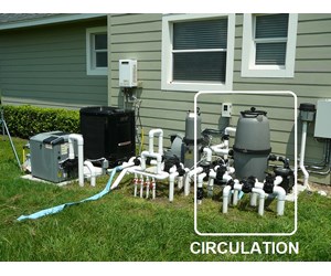
The pool equipment required for circulating the pool and spa water through a filtering system is shown on the right side of this picture. This equipment consists of the circulation pump, a large filter and the valves and piping required to command the catamenia of h2o from and to the pool and spa.
Step 2
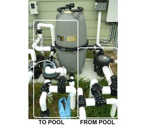
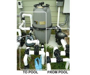
This picture provides a closer view of the circulation equipment. The circulation equipment is frequently broken into 2 sections: "From Pool" - the suction side of the pump that pulls water from the puddle; and "To Pool" - the discharge side of the pump that pushes water back through the filter to the return ports of the pool. We'll talk over the "From Pool" equipment showtime.
Please click hither to view diverter valves.
Step 3
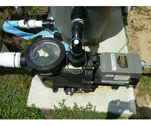
This is a picture of the chief apportionment pool pump - a Jandy 2HP variable speed E-Pump JPR two.0. It operates at speeds of betwixt 1725 and 3450 RPM to conserve energy. H2o from the puddle comes into the pump on the left side of the picture and is discharged to the filter through a port on the elevation of the pump. Click here for more data on "How a Pool Pump Works".
Please click here to view pumps.
Step 4
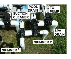
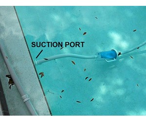
For this big puddle h2o is sucked into the puddle pump from v unlike sources; the puddle bleed, the spa drain, skimmer one, skimmer 2 and a port to the suction pool cleaner. Iv valves are installed to allow the user to select which of these sources to pull from.
Pace five
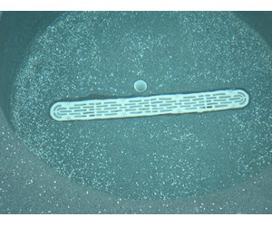
Spa Drain - the long white strip on the bottom of the spa. This long drain is one of the newer products designed to avoid entrapment by suction.
Step six
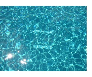
Puddle Drains - the white strips at the lesser of the pool. Two were installed for this pool arrangement: one for supplying h2o to the main circulation pump and one for supplying water to the characteristic's pump discussed in Part 2 - Features. Both of these drains collect debris off the bottom of the pool.
Please click here to view skimmers and chief drains.
Step vii
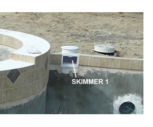
Skimmers - Two skimmers were installed around the circumference of this pool because of its size and style. Most pools merely have 1 skimmer. Skimmers are used to collect debris off the surface of the puddle.
Pace viii
Step 9
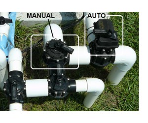
Valves can be installed for either manual operation or automatic functioning. For transmission functioning, you set up the handle manually to open or shut selected ports. In an automated operation, a valve actuator is mounted on top of the valve and the valve is controlled digitally through a command box. For more information on valves click
hereDelight click hither to view valve actuators.
Step ten
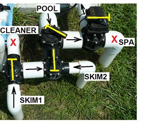
This picture shows a common valve setting for this pool. The yellowish "T" lines placed over each valve show the position of the valve handles. If the handle is placed so that the meridian of the "T" is across a pipe, that port is airtight - as is the example for the pool cleaner and the spa drain. If the handle is placed with the summit of the "T" running in line with the piping, all ports are open up. If the "T" is at an angle to the pipe, the valve is allowing partial menstruation through the port - as is the case with the pool drain. In this item valve configuration water is flowing to the pump from the two skimmers and partially from the puddle bleed. Water from the spa bleed and the pool cleaner is blocked. When the suction cleaner is used, the skimmer ports are close off to provide more suction to the cleaner.
Step 11
"To Pool" - The second one-half of this guide discusses the discharge side of the pump - water beingness pushed from the pump, through the filter, and back to the pool.
Step 12
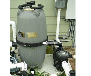
H2o is discharged from the pump into the pool filter. A big Jandy TL 580 Cartridge Filter with 4 cartridges was selected to filter this large of a pool.
Please click hither to view filters.
Step 13
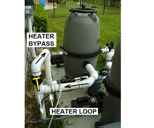
After the water is filtered, it flows to a valve that diverts the h2o through a heater loop if desired. If not, the valve is set to have the water bypass the heaters and menstruation directly to the system's chemic treatment equipment. The xanthous "T" superimposed on the valve shows that the valve is set to divert the h2o through the heater loop. Meet Role 3 for an expanded word of this puddle's Heaters.
Please click here to view heaters.
Step 14
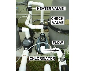
This pool system uses a fully automated chemical organization to command the chlorine and pH levels. See Office four for an expanded discussion of the Chemical equipment. Note that a check valve has been inserted just before the Chlorinator. This valve only allows the water to flow in one management. Sometimes when the pumps is shut off, backpressure is created that may push button the h2o backward. This valve keeps the undiluted chlorine water from bankroll up into and damaging the heater and filter systems.
Please click here to view check valves.
Please click here to view sanitizers.
Step 15
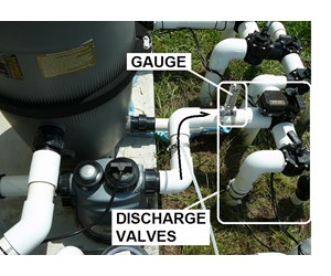
From the Chlorinator the h2o flows to a series of diverter valves that directly the water to the various return ports in the pool. Annotation the Flow Approximate inserted in the pipe just before the diverter valves.
Delight click here to view diverter valves.
Step 16
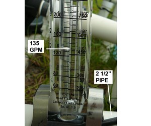
This Flow Gauge monitors the water pressure in the pipe to alert the user to a possible water flow problem like a partial blockage or the demand to clean the filter. Information technology is likewise used to help residuum the line to provide optimum pressure in the line. These gauges come in different models according to the size of the pipe. In this case the gauge is calibrated for a ii 1/2" pipe and is currently reading at 135 GPM.
Please click here to view menstruum meters.
Stride 17
Stride 18
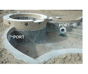
Pool Return Jets - This picture shows the location of ii of the render jets in the side of the puddle. the other iii are positioned about equally spaced around the puddle.
Step 19
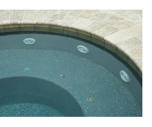
Spa Return Jets - This picture shows the location of 3 of the 8 Spa jets that provide water to the Spa. The loftier pressure normally associated with these jets is created when air pressure is injected into the water streams by an air blower. This is discussed further in Part 2 - Features.
Step 20
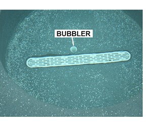
Spa Bubbler - This port supplies water to the Spa to provide some fresh water circulating in the Spa when the Spa is shut off. When the Blower is turned on, information technology becomes a Bubbler.
Step 21
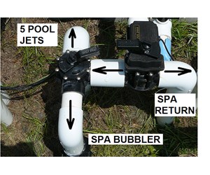
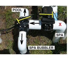
This movie shows a common configuration for return valves when the Spa is not in use. The yellowish "T" lines placed over each valve testify the position of the valve handles. H2o to the Spa return ports is blocked and water is flowing to the 5 Pool Jets and the Spa Bubbler. Notation that by the positioning of the handle more water is flowing to the Pool Jets than the Spa Bubbler.
Step 22
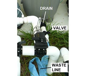
There is one port left in the discharge side that has to be addressed withal and that is the Waste matter line coming out at the bottom of the circulation filter. This port is opened past a Ball Valve to dump water from the pool after a heavy rain or to drain the pool for any other reason.
Please click here to view ball valves.
Pace 23
This concludes our guide on setting up equipment for in footing puddle circulation. Click here to return to the Overview for other pool equipment options.
How To Set Up A Swimming Pool Pump,
Source: https://www.inyopools.com/HowToPage/how_to_set_up_in_ground_pool_equipment_part_1_circulation.aspx
Posted by: gibbsartmer.blogspot.com


0 Response to "How To Set Up A Swimming Pool Pump"
Post a Comment